 Steam power was the result of several developments associated with the Industrial Revolution. The invention of malleable iron by Henry Cort in 1784 certainly provided the means of shaping iron for power-plant production, as did the work of machinist David Wilkinson and others.
In the late eighteenth century, Boulton & Watt established an engine manufacturing plant that eventually provided an opportunity for European and American engineers to experiment with steam-power propulsion.
In the United States, John Fitch experimented with marine steam power on the Delaware River near Philadelphia, while John Stevens and Robert Fulton worked between New York and Hoboken, New Jersey.
 Colonel Stevens operated a steam launch at Hoboken in 1804. When Fulton built the world’s first commercially successful steamboat, North River Steam Boat, in 1807, he had little idea what the appropriate hull form should be. The vessel seems to have had a shape similar to a large canal boat or a sailing ship.
In describing the boat, enrollment records state “she is a square-sterned boat, has a square tuck: no quarter galleries and no figurehead.”
The vessel, built at the Charles Brown Shipyard on the East River near Manhattan, originally measured 140 feet in length by 16 feet in breadth, a ratio of almost 1 to 10. The copper boiler (low-pressure) measured 20 feet long by 8 feet wide.
Rebuilt after its first season, the steamboat measured 149 feet. Peter A. Schenck, Surveyor of the Port, certified that the boat had one deck and two masts, a breadth of 17 feet 11 inches, and a 7- foot depth. A contemporary drawing of the boat, later named North River, shows a stem similar to those on sailing ships of the period, though with a proportionately wider transom.
The paddlebox extended out from the hull with no additional structure forward or aft. There are two masts, one forward and one aft, with yards for square sails, which are furled.
 Jean Baptiste Marestier‘s study of American steamboats, Memoir on Steamboats of the United States of America, published in Paris in 1824, includes an outboard profile of Fulton’s steamboat Paragon, built for the Hudson River in 1811.
It is very similar to the drawing of North River described above. The sails are shown set with a very deep square sail on the foremast, a small square topsail above, and a fore-and-aft sail from a gaff and boom on the second mast set.
It has a plain bow with a convex curve to the stem, and a bowsprit house on deck from which is set a single jib. The main difference from the first steamboat is the apparent addition of “guards,” protective moldings flared out around the paddlebox.
Paddlewheels
Ship paddlewheels, called waterwheels at the time, had the same basic design as waterwheels used in powder mills. These wheels were easily modified for marine use.
To generate enough thrust from a relatively slow-turning steam engine, screw propellers had appreciable draft, creating problems for a shallow-draft vessel. On a shallow-draft hull, a pair of paddlewheels generated ample thrust without projecting below the keel line.
The 1820s witnessed two major changes in steamboat design. Sails disappeared within a few years, and length-to-breadth ratios declined (7 to 1 or less). Aside from these developments, boats of the early 1820s had most of the same features as the Paragon.
The Constitution, built in New York, had a similar bow and a transom stern with six or seven windows. The guards around the paddleboxes did not extend very far forward or aft, but did create some additional space for storing boiler wood. The vessel included a second deck aft of the engine, sheltered by an awning.
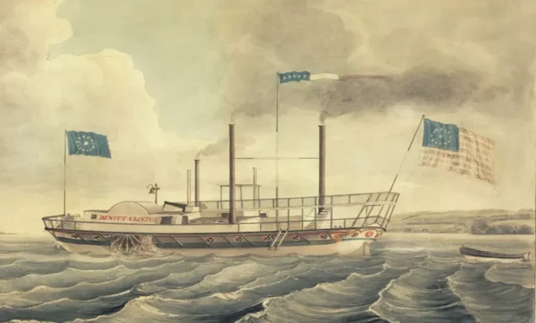
 The DeWitt Clinton, built at Albany in 1828, measured 233 feet in length, 28 feet in beam, 64 feet over the guards, 10 feet depth of hold, and 4.6 feet draft. Freeboard reduction brought the main deck much closer to the water and little transom remained at the stem.
The guards extended outboard around the paddleboxes in a continuous curve from bow to stem, supported at intervals by diagonal struts braced against the hull.
In addition to providing more space, the guards afforded a practical place to put the boilers. West Point Foundry built the engine, the largest at the time, with cylinders measuring 66 inches in diameter with a 10-foot stroke.
In 1824 Marestier expressed concern over the stress engines and boilers placed on wooden hulls of this type once they exceeded a certain length.
Several methods provided additional support. A heavy-timbered truss ran fore and aft on either side, with the highest point sometimes arching over the paddlewheels. These trusses, called hogframes, were a distinctive feature on early wooden-hulled steamboats.
The De Witt Clinton also had three masts on the centerline supporting “hogging chains,” iron rods extending to either side, offering additional support for the guards. These rods distributed the stress and provided support for the guards.
Additionally, the wooden hulls were equipped with massive engine bed timbers because of the engine’s great weight.
Crosshead engines powered early steamboats. Developed from Fulton’s basic vertical-cylinder layout, this type of engine is named after its crosshead frame. A long piston rod extended above the cylinder to form a T with the horizontal crosshead.
 The crosshead, a device forming a connection between the piston rod and connecting rod, is similar to the joints in the human body. The engine, positioned athwartships, moved and up and down on vertical guides.
The first guides were mounted on simple upright timbers. Later a pair of A-frames (linked together at the top) replaced these timbers. Some steamboaters called it the “gallows frame” because of its shape.
Near the outer ends of the crosshead, two connecting rods attached together. These came down on either side of the cylinder to crank throws on the paddlewheel shafts. As the crosshead rose and fell, the connecting rods rotated the cranks, turning the wheels.
The vertical beam engine, known as the “walking beam,” is a uniquely American technology. Developed around 1820, the engine’s design was used as late as the 1950s.
Its popularity revolved around its simplicity, although fewer were made. Introduced as a solution for space and balance problems associated with bigger engines, the walking beam engine also had a vertical cylinder.
A piston rod attached to a crosshead above; above the crosshead, a second rod connected to one end of a diamond-shaped beam. The beam rotated at its center on a bearing mounted at the top of an A-frame, similar to the A-frame of earlier engines.
A connecting rod to the single crank throw was attached to the other end of the diamond-shaped beam. In this way the beam, rocking back and forth, transferred the up-and-down motion of the piston to the crank, turning the paddlewheels.
 The walking beam apparently got its name from the rate at which it moved, usually in full view above the roof of the steamboat’s uppermost deck.
In a few later steamboats, it was enclosed in a small uppermost deck. Later still, it was enclosed in a small, greenhouse-like structure.
By the mid-1800s, wrought-iron straps over a cast-iron framework replaced heavy wooden timbers, though wooden frames appeared right up to the end of the walking beam era. In the 1880s, A-frames consisted of iron and then steel angular plating.
Three known examples of the walking beam engines survive, two in the United States: the ferry Eureka, preserved at San Francisco, and the lake steamer Ticonderoga, preserved at the Shelburne Museum in Vermont.
Read more about New York steamboats.
This essay is excerpted with minor editing for clarification from Target Investigations in Connection with the New York and New Jersey harbor Navigation Project, May 2004, prepared for the U.S. Army Corps of Engineers, New York District, by Andrew D.W. Lydecker and Stephen R. James, Jr. of Panamerican Consultants, Inc.
Illustrations, from above: Statue of Boulton, Watt and Murdoch in Birmingham, England; The 1909 replica of the North River Steamboat (Clermont) at anchor; Steamboat Paragon, constructed in 1811 (1824 drawing from Memoir on Steamboats of the United States of America); Crosshead engine diagram of steamboat Belle from Frederick Remsen Hutton’s The Mechanical Engineering of Power Plant, 1897; Steamboat DeWitt Clinton (detail), 1825-1850, by Richard Varick DeWitt, 1800-1868 (courtesy Albany Institute of History and Art); Walking beam engine from Robert Henry Thurston, A History of the Growth of the Steam-engine, 1887.
Source link